How To Size A Digester
The piping system connects the biogas plant with the gas appliances. It has to be safe, economic and should allow the required gas-flow for the specific gas appliance. Galvanized steel (G.I.) pipes or Polyvinyl chloride (PVC) pipes are most commonly used for this purpose. Most prominently, the piping system has to be reliably gas-tight during the life-span of the biogas unit. In the past, faulty piping systems were the most frequent reason for gas losses in biogas units.
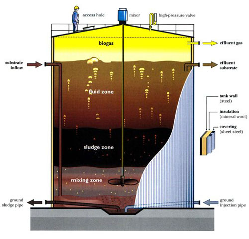
Building a simple two-barrel anaerobic digester. Friday, 10th February 2012. This computer animation shows just how easy it is to build a biodigester to create flammable biogas from animal/food waste. Simple plastic tubing, two plastic barrels and some patience are all it takes to produce - according to its creators - around two. Modern farm-size digesters. Design characteristics and operating experiences have been reported for a number of farm-size digesters currently or formerly in operation in a number of locations (Table 1). Some are pictured in Figures 1 to 5. Scaling of the digester The size of the digester i.e. The digester volume is determined by the length of the retention time and by the amount of fermentation slurry supplied daily. The amount of fermentation slurry consists of the feed material (e.g., cattle dung) and the mixing water. Sizing the Digester The size of the digester, i.e. The digester volume Vd, is determined on the basis of the chosen retention time RTand the daily substrate input quantity Sd. m3= m3/day × number of days The retention time, in turn, is determined by the chosen/given digesting temperature.
Polyvinyl chloride (PVC) pipes and fittings have a relatively low price and can be easily installed. They are available in different qualities with adhesive joints or screw couplings (pressure water pipes). PVC pipes are susceptible to UV radiation and can easily be damaged by playing children. Wherever possible, PVC pipes should be placed underground.
Galvanized steel (G.I.) pipes are reliable and durable alternatives to PVC pipes. They can be disconnected and reused if necessary. They resist shocks and other mechanical impacts. However, galvanized steel pipes are costly and the installation is labor intensive, therefore they are only suitable for places where PVC is unavailable or should not be used.
The necessary pipe diameter depends on the required flow-rate of biogas through the pipe and the distance between biogas digester and gas appliances. Long distances and high flow-rates lead to a decrease of the gas pressure. The longer the distance and the higher the flow rate, the higher the pressure drops due to friction. Bends and fittings increase the pressure losses.G.I. pipes show higher pressure losses than PVC pipes. Table 1 gives some values for appropriate pipe diameters. Using these pipe diameters for the specified length and flow rate, the pressure losses will not exceed 5 mbar.

| Galvanized steel pipe | PVC pipe | |||||
|---|---|---|---|---|---|---|
| Length [m]: | 20 | 60 | 100 | 20 | 60 | 100 |
| Flow-rate [m3/h] | ||||||
| 0.1 | 1/2' | 1/2' | 1/2' | 1/2' | 1/2' | 1/2' |
| 0.2 | 1/2' | 1/2' | 1/2' | 1/2' | 1/2' | 1/2' |
| 0.3 | 1/2' | 1/2' | 1/2' | 1/2' | 1/2' | 1/2' |
| 0.4 | 1/2' | 1/2' | 1/2' | 1/2' | 1/2' | 1/2' |
| 0.5 | 1/2' | 1/2' | 3/4' | 1/2' | 1/2' | 1/2' |
| 1.0 | 3/4' | 3/4' | 3/4' | 1/2' | 3/4' | 3/4' |
| 1.5 | 3/4' | 3/4' | 1' | 1/2' | 3/4' | 3/4' |
| 2.0 | 3/4' | 1' | 1' | 3/4' | 3/4' | 1' |
The values in table 1 show that a pipe diameter of 3/4' is suitable for flow rates up to 1.5 m3/h and distances up to 100 m (PVC pipe). Therefore one could select the diameter of 3/4' as single size for the hole piping system of small biogas plants. Another option is to select the diameter of l' for the main gas pipe and 1/2' for all distribution pipes to the gas appliances.


PVC can be used for all underground pipes or pipes that are protected against sun light and out of the reach of children. For all parts of the piping system that are above ground one should install galvanized steel pipes. Therefore it is recommended to use l' G.I. steel pipes for the visible part of the piping system around the biogas digester. For the main pipe one uses l' PVC pipe placed underground. The distribution pipes should be 1/2' G.I. steel pipes or PVC pipes, depending whether they are installed above or under the wall plastering. But even though G.I. pipes are less susceptible to damage, placing them underground should always be the preferred solution.
PVC pipes have to be laid at least 25 cm deep underground. They should be placed in a sand bed and be covered with sand or fine earth. One should carefully back-fill the ditches in order to avoid stones lying directly above the pipe.
When the piping is installed - and before refilling the ditches - it has to be tested for possible gas leakage. This can be done by pumping air into the closed piping system up to a pressure that is 2.5 times the maximum gas pressure of the biogas plant. If pressure loss occurs within few hours, every joint of the piping system has to be checked with soap water. Soap-bubbles indicate any leakage of gas.
Due to temperature changes, the moisture-saturated biogas will form inevitably condensation water in the piping system. Ideally, the piping system should be laid out in a way that allows a free flow of condensation water back into the digester. If depressions in the piping system can not be avoided, one or several water traps have to be installed at the lowest point of the depressions. Inclination should not be less than 1%.
Piping system with straight slope from kitchen to digester. No water trap required as condensation water drains into the digester[1] |
How To Size A Digester System
| Wherever condensation water cannot drain back into the digester, a water trap becomes necessary[1] |

Size Determination Sba
Often, water traps cannot be avoided. One has to decide then, if an 'automatic' trap or a manually operated trap is more suitable. Automatic traps have the advantage that emptying - which is easily forgotten - is not necessary. But if they dry up or blow empty, they may cause heavy and extended gas losses. In addition, they are not easily understood. Manual traps are simple and easy to understand, but if they are not emptied regularly, the accumulated condensation water will eventually block the piping system. Both kinds of traps have to be installed in a solid chamber, covered by a lid to prevent an eventual filling up by soil.
| Automatic water trap[1]: (1) T-joint in the piping system, (2) water column, equal to max. gas pressure + 30% security, (3) solid brick or concrete casing, (4) concrete lid, (5) drainage |
| Manual water trap[1]: (1) T-joint, (2) buffer storage for condensated water, (3) manual tap, (4) casing, (5) concrete lid, (6) drainage |

To the extent possible, ball valves or cock valves suitable for gas installations should be used as shutoff and isolating elements. The most reliable valves are chrome-plated ball valves. Gate valves of the type normally used for water pipes are not suitable. Any water valves exceptionally used must first be checked for gas-tightness. They have to be greased regularly. A U-tube pressure gauge is quick and easy to make and can normally be expected to meet the requirements of a biogas plant.
The main gas valve has to be installed close to the biogas digester. Sealed T-joints should be connected before and after the main valve. With these T-joints it is possible to test the digester and the piping system separately for their gas-tightness. Ball valves as shutoff devices should be installed at all gas appliances. With shutoff valves, cleaning and maintenance work can be carried out without closing the main gas valve.
- ↑ 1.01.11.21.3http://www.ewb-usa.org/files/2015/05/BiogasConstructionTraining-handout.pdf
1. Introduction
A biogas plant is an anaerobic digester of organic material for the purposes of treating waste and concurrently generating biogas fuel. The treated waste is a nutrient-rich, nitrogen-rich fertilizer while the biogas is mostly methane gas with inert gases including carbon dioxide and nitrogen. Biogas plants are a preferred alternative to burning dried animal dung as a fuel and can be used for the treatment of human waste. Other feedstock which can be used includes plant material, non-meat or grease food-wastes, and most types of animal dung. Over a million biogas plants have been constructed in the developing world for treatment of organic wastes, alternative energy supply to direct burning in the home, and overall improvement of human health and the environment. Many factors for selection of feedstock and site location must be researched before deciding to install a biogas plant. Successful construction of the biogas plant requires a proper design and adherence to follow correct construction methods. The success or failure of any biogas plant primarily depends upon the quality of construction work. The following instructions are based on the step-by-step instructions from the Government of Nepal Biogas Support Program Gobar Gas and Agricultural Equipment Development Company of Nepal has developed the design for model 2047 biogas plant. This biogas plant model has become prolific across Asia and is known as a fixed-dome plant. The advantages of the fixed dome plant include the simplicity of design, few moving parts, low cost to construct and low maintenance. The disadvantages when compared to a floating-dome digester are primarily the inability to store gas for use on demand; gas from the fixed dome digester must be used as generated or expelled to avoid damaging the digester.
2. Determining Plant Size
This manual includes design and construction material quantities for the Gobar biogas plant models of 4, 6, 8, 10, 15 and 20 cubic meters capacity. Design and size of a plant other than mentioned above is feasible and a skilled engineer should be consulted for deviations from the provided designs. The biogas plant size is dependent on the average daily feed stock and
expected hydraulic retention time of the material in the biogas system. Generally, 24 kilograms of feedstock complimented with 24 liters of water per day with a hydraulic retention time of 35 days will require a 4-cubic meter plant. Table 2.1 below gives some relevant data about the six different sizes of biogas plants presented in this manual.
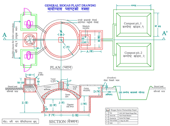
The biogas plant detailed in this manual consists of five main structures or components: 1. InletTank; 2. Digester Vessel; 3. Dome; 4. Outlet Chamber; and 5. Compost Pits. The required quantity of feedstock and water is mixed in the inlet tank and the slurry is discharged to the digester vessel for digestion. The gas produced through methanogenesis in the digester is collected in the dome. The digested slurry flows to the outlet tank through the manhole. The slurry then flows through the overflow opening in the outlet tank to the compost pit. The gas is supplied from the dome to the point of application through a pipeline.When a biogas plant is underfed the gas production will be low; in this case, the pressure of the gas might not be sufficient to fully displace the slurry in the outlet chamber. It is important to design the plant keeping hydrostatic pressure higher at the inlet tank than the outlet tank. The hydrostatic pressure from slurry in the inlet and outlet tanks will pressurize the biogas accumulated in the dome. If too much material is fed into the digester and the volume of gas is consumed, the slurry may enter the gas pipe and to the appliances.
